Author — Strunkin G. N. (engineer at PrJSC, Zaporizhzhia)
Issued:
Magazine "Ukrainian Railway" ("Ukrzaliznytsia"). - 2017. - № 11-12 (53-54). - P. 55-58
Annotation. Leading experts of Ukrainian enterprises do their work for the long run, researching railway transport needs. Range of converters with overfrequency link for railway is developed with application of software and technologies.
Key words: overfrequency link, inverter, transformer, operating current cabinet, uninterruptible power supply system, galvanic insulation.
Introduction
Nowadays with appearance of new semiconductor devices, increased high-speed operation of microcontrollers and implementation of new control algorithms, it is now possible to use extensively new classes of converter units with overfrequency link. It allows significantly reducing weight and size factors, and in other instances to change fundamentally approach to development of standard systems in railway engineering. All the above-mentioned is positively influenced by application of modern simulation software that allows avoiding mistakes during the design phase, that further reduces product development costs.
PLUTON experts monitor innovations on the market of electronic components and articles published in field-specific editions. It allows keeping development and implementation of power electronics devices on the most modern level. Development of range of products with overfrequency conversion for railway needs is a great achievement of PLUTON Company. Current range of products includes:
- traction converter;
- charging unit;
- operating current cabinet SHOT1М;
- uninterruptible power supply systems for various powers;
- power supply units for processing plants of various purpose;
- blowers, compressors, pumps automatic control systems, as well as automatic climate control systems based on that systems;
- synchronous electric machines excitation systems.
Main point of overfrequency conversion
Method of overfrequency conversion is outlined as follows: input DC voltage with application of transistor inverter (half-bridge or bridge) is converted into overfrequency AC voltage (2.5 kHz and higher), further it comes onto high-frequency matching transformer that pulls it down to required value and performs galvanic insulation. Obtained voltage is converted into DC voltage due to rectifier with high-speed diodes. As a rule, LC-filter is installed at the rectifier outlet for reduction of high-frequency pulsation component.
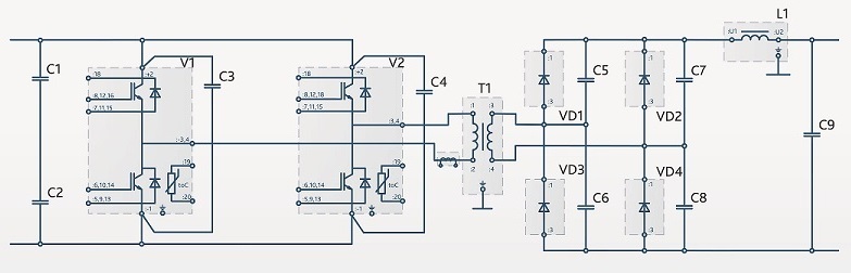
Pic. 1 Simplified diagram of converter with overfrequency link
Converter has input current and voltage feedback. Input voltage, transformer current, components temperature and a number of other parameters are also controlled. Measurement of electrical values is carried out via Hall effect sensors. Insulation of inverter transistors control impulses is optical. Furthermore, intelligent blowers control according to temperature and current sensors is applied in the converter. As a rule, IGBT transistors are applied in inverter.
If operation of unit from AC network is required, diode rectifier and auxiliary components are additionally installed in front of inverter: input capacitors charging unit, interference filters, switching equipment.
Application of high-frequency transformer allows significantly reducing weight and size factors of power supply units in comparison with standard diagrams that use conversion on a frequency of 50 Hz. For example, standard synchronous motor exciter that operates on a frequency of 50 Hz with a capacity of 25 kW is about 180 kg heavier and costs about twice as much as exciter with overfrequency conversion.
Traction converter
Instead of outmoded DC drive for car pusher in 2012 PLUTON developed traction AC drive for contact network 1.65 kV with capacity of 2х80 kW.
Traction converter structurally consisted of two cabinets: voltage converter cabinet — DC/DC converter of 1.65 kV voltage into 550 V voltage with galvanic insulation, and cabinet with voltage inverters SHIN — directly frequency-controlled electric drive of asynchronous traction motors. We will not pay too much attention to detailed description of cabinet with voltage inverters SHIN (its operation is similar to other frequency traction electric drives) and provide some characteristics of voltage converter cabinet:
- input voltage — 1,5...2 kV;
- output voltage — 550 V;
- rated power — 2х80 kW;
- conversion frequency — 3 kHz.
Cabinet diagram was represented as converter that consists of half-bridge inverter, high-frequency transformer and rectifier. Cooling of all main circuit components is forced air. Converter operated in the 550 V DC voltage regulation mode.
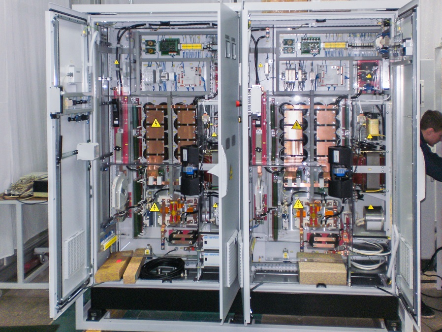
Pic. 2 Voltage converter cabinet during tests
Nowadays, with development of components base it is possible to develop of traction DC/DC converters and asynchronous electric drive for switching electric locomotive, as well as for auxiliaries converters for main-line electric locomotives, diesel trains and electric trains applied in all contact networks of railway transport.
Charging unit
Charging unit is provided for charging of accumulator battery and power supply of secondary circuits of railway substations with DC voltage both in float accumulator batteries service, and directly.
Charging unit implements methods of accumulator batteries IU, U, IUI charge in accordance to DIN41773.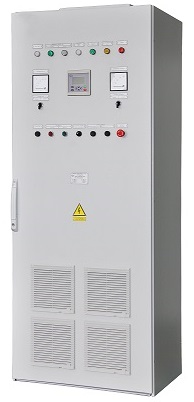
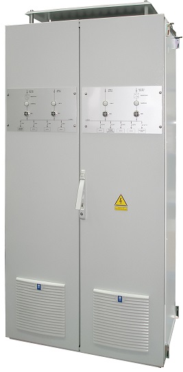
Pic. 3 Exterior of charging unit
Requirements to electrical parameters of charging unit:
- three-phase rated output voltage — 380 V;
- supply voltage variation range — 323-418 V;
- output voltage — 110 and 230 V;
- output voltage variation range (if adjustment is required) — 90-120 и 200-240 V;
- output current — 100 А;
- conversion frequency — 18 kHz.
In addition to the standard protection against external and internal short circuit, overheating and overloads, charging unit should obligatory contain monitoring of insulation of positive and negative pole of output voltage relative to the ground. There is also automatic reclosing mode.
Charging unit is provided with connection of air temperature sensor in the area of accumulator location for adjustment of battery charge voltage. This unit can simultaneously operate with other similar device.
Operating current cabinet SHOT1M
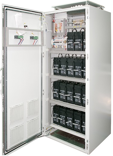
Operating current cabinet based on high-frequency voltage converter that fulfills a function of charging and rectifying unit provided for conversion of AC into AC into regulated DC for charging of accumulator batteries and power supply of consumers with DC voltage both at buffer connection with accumulator battery and directly. Application area — railways traction substations and other railway facilities that need accumulator batteries for secure power supply.
SHOT1M allows operation from network of 220 V or 380 V. Thereby, single-phase design is also possible. Accumulator battery capacity can amount up to 1000 А·hours. Operation from one or two inputs is also possible.
SHOT1M implements methods of accumulator battery charge IU, U, IUI according to DIN41773. SHOT1M provides parallel operation with similar converters under total load. Just as in charging unit, SHOT1M provides full charging circuit protection set. 2-modular design with 100 % parallel redundancy is also covered. Number of automatic circuit breakers and other switching units is installed according to Customer’s requirements.
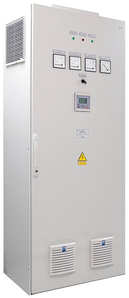
Pic. 4 Exterior of operating current cabinet SHOT1M
Uninterruptible power supply systems
For facilities that require secure qualitative and stable AC voltage PLUTON experts developed uninterruptible power supply systems range. Uninterruptible power supply system is provided for uninterruptible power supply of consumers with regulated AC three-phase voltage. Uninterruptible power supply system is available for capacity range from 15 up to 60 kVА. It can be developed for capacity of up to 500 kVА if required.
Uninterruptible power supply systems include the following cabinets:
- converters and switching cabinets;
- accumulator battery cabinet.
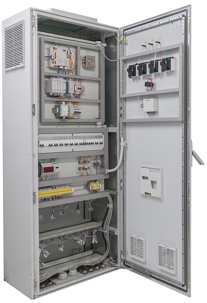
Pic. 5 Equipment of uninterruptible power supply systems
Converters and switching cabinet consists of charging and rectifying unit, voltage inverter with sinus filter, redundant (bypass) supply channel, matching transformers. High-powered equipment is installed separately from each other in several cabinets.
Uninterruptible power supply system operates under three modes:
- “normal” mode — power is consumed from main input and converted into DC voltage. Further, stand-alone inverter produces voltage for power supply of connected load.
In this mode inverter simultaneously operates with network. If network frequency exceeds tolerance limit, inverter will switch over to own synchronization.
- bypass “mode” — load power supply is carried out via redundant input.
Switching to this mode is carried out automatically, without any load power supply interruption in the following cases:
- inverter overload;
- inverter failure;
- with delay for the case of supply loss at main input;
- internal temperature exceeds maximum permitted value.
- “accumulator mode” — upon no voltage in supply network at both inputs uninterruptible power supply system keeps providing load power supply, using power stored in accumulator batteries.
Uninterruptible power supply system can operate both from network, and together with substation diesel generator unit, providing substation circuits power supply from accumulators for the time required for diesel motor start.
Power supply units of various purpose
Various power supply units can be developed based on converter with overfrequency link:
- for excitation of synchronous machines;
- for electrotechnological facilities (galvanics, electrolysis, electrochemistry);
- for welding;
- for impulse generators.
All these power supply units have the following benefits in contrast to standard thyristor units, operating upon frequency of 50 Hz:
- improved weight and size factors;
- high power factor and slight impact on power network;
- high-speed operation upon external short circuits;
- reduced materials consumption (copper, transformer steel);
- reduced acoustic noise (except traction converters).
These units can be applied for improvement of operation of substations diesel-generator units while modernization of equipment of railway shops, electric locomotive repair plants and other facilities.
Blowers, compressors, pumps automatic control systems and microclimate automatic control systems on their basis
Frequency converters with pulse-width high-frequency modulation of output voltage are traditionally used in the blowers, compressors, pumps and microclimate automatic control systems. The advantage of this complex lies in the fact that all equipment is combined into unified automatically controlled complex using specially designed control system. Several parameters that further are automatically kept at the set level are set for this complex.
Application area of automated control system is broad ranging. It is used in any cases, when improvement of natural climatic conditions is required — railroad cars and locomotives, rooms of stations, substations, shops, workshops, underground facilities and other facilities.
МС-40 control system
МС-40 microprocessor system developed by PLUTON controls all converters with overfrequency link. It allows implementing processing algorithms of the most complicated level.
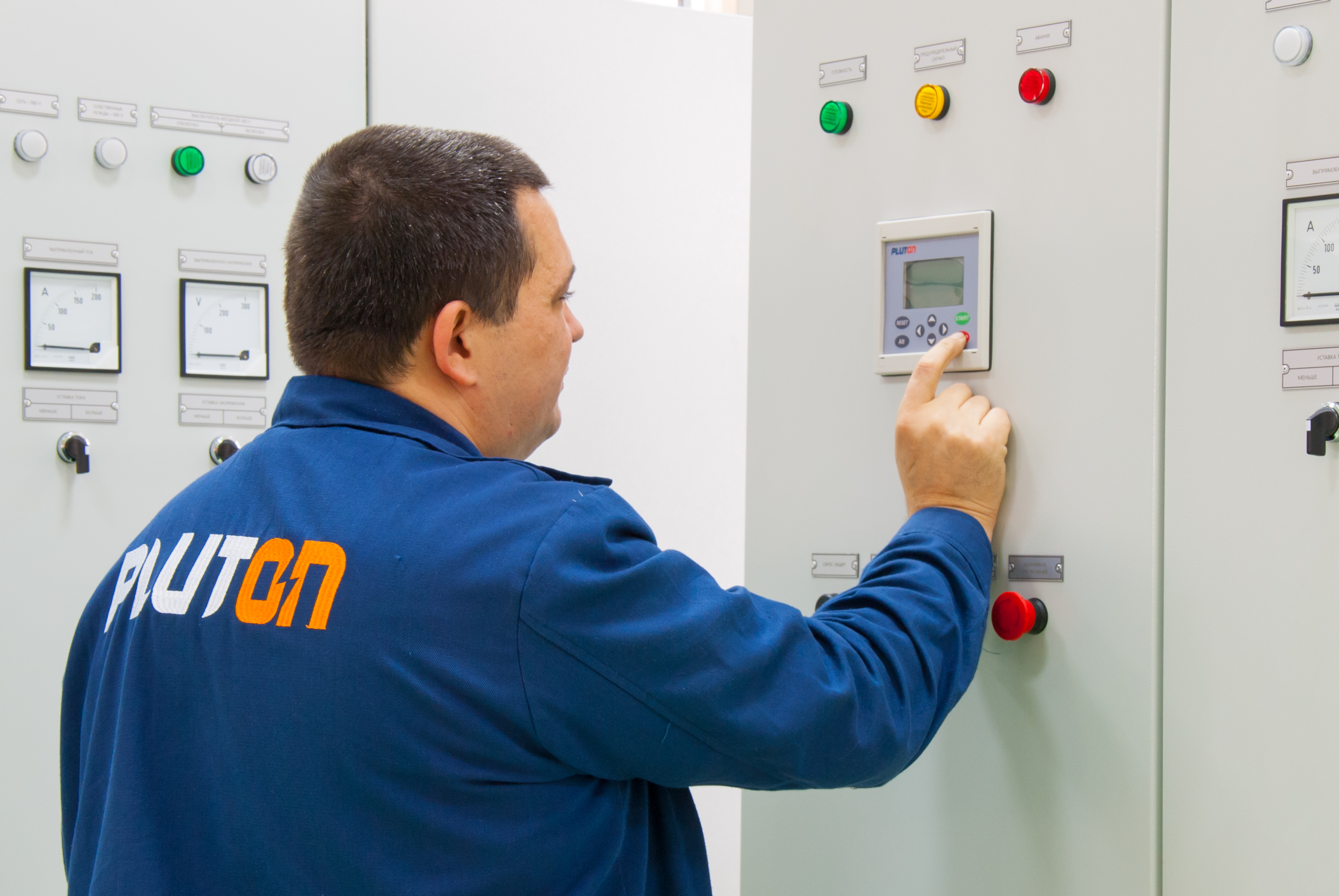
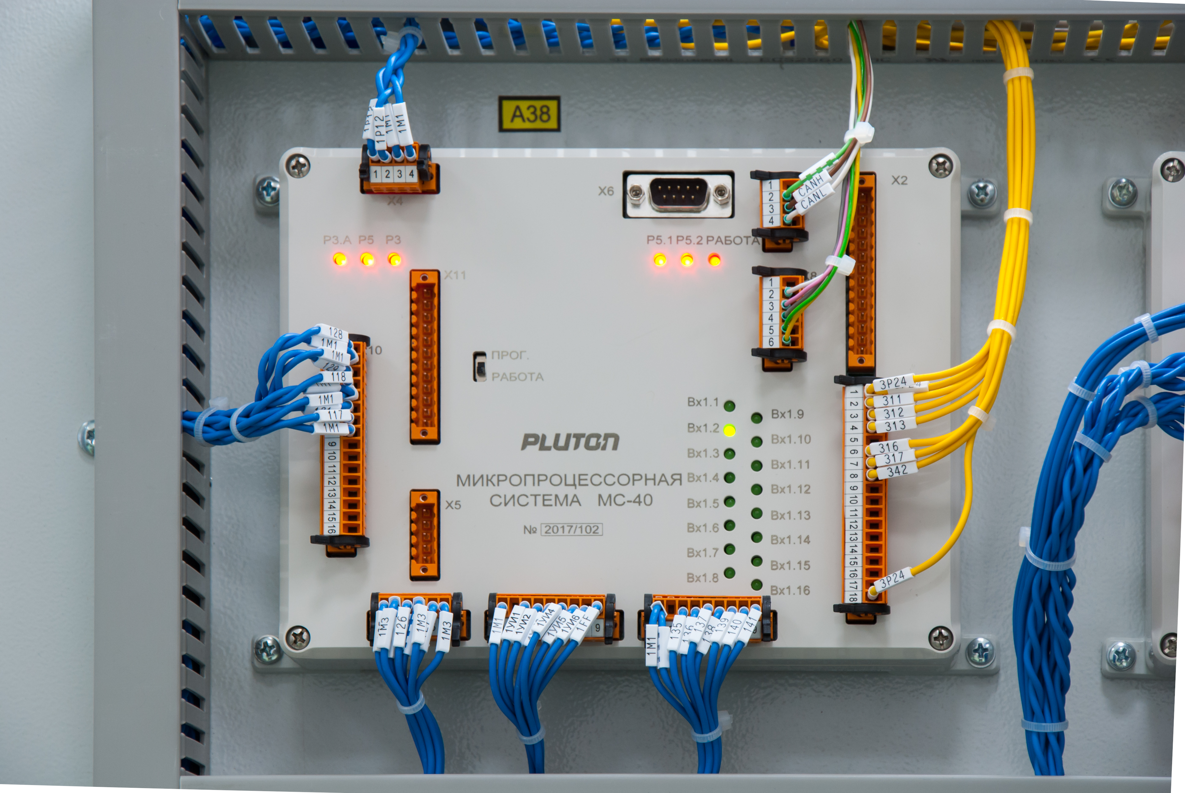
Pic. 6 Exterior of control system and control terminal
The system is developed based on modern signaling processor. It consists analog and discrete inputs and outputs, communication port, timer and operation display. МС-40 contains non-volatile memory that allows storing emergency log, emergency "trace" that is convenient upon analysis of technological out-of-specification situations reasons.
Presented PLUTON products based on converter with overfrequency link, are modern knowledge intensive examples of electrical engineering. Application area of these products is not limited to already specified applications that is why PLUTON experts already do their work for the long run, researching railway transport needs.
Issued:
Magazine "Ukrainian Railway" ("Ukrzaliznytsia") - 2017. - № 11-12 (53-54). - P. 55-58